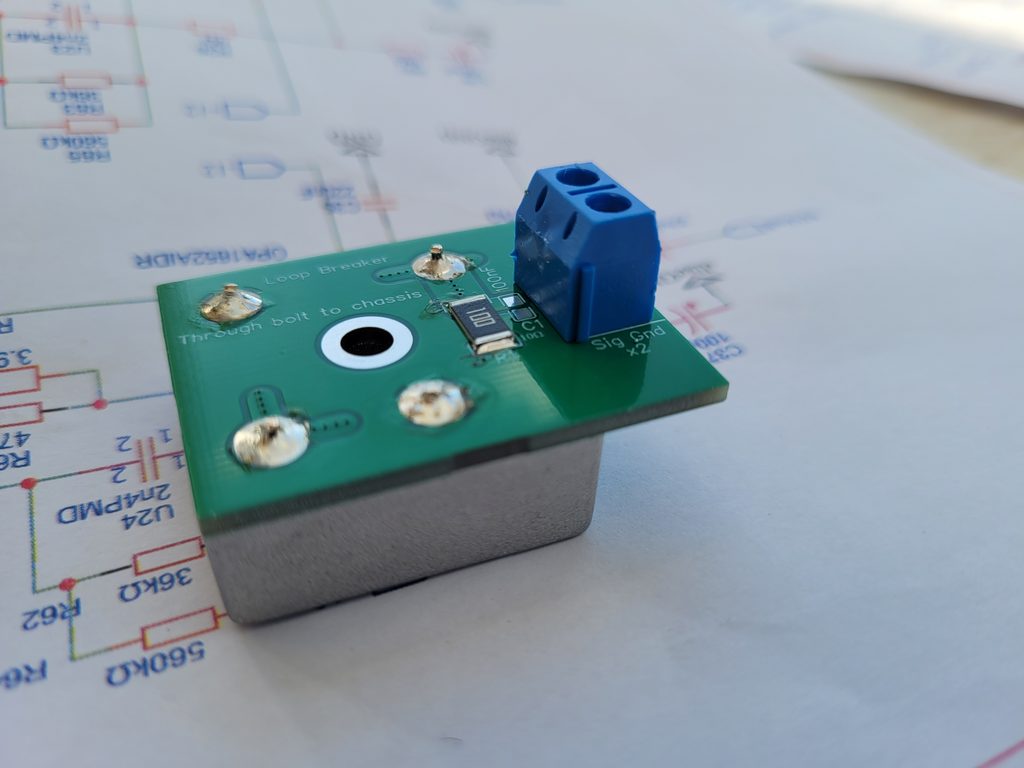
It is well known that two mains grounded amplifiers used together will create a ground loop causing substantial hum through the speakers. NEVER remove a safety earth to break the loop.
Old Crimson monoblocks were mains grounded and suffered from this problem. Even the mains grounded stereo amps could have a hum loop if fed from a grounded source such as an FM tuner. The PCB described here safely eliminates ground loop problems but should only be installed by someone with full knowledge of safe wiring practice.
The PCB consists of 35A rectifier wired to create a heavy duty anti-parallel diode link between the signal ground and the amplifier power ground. There is a 10 Ohm resistor to electrostatically earth the power ground.
How to use:-
- Make sure the amplifier internal ground is isolated from the chassis. This may entail changing input phono sockets to isolated types.
- Drill a hole in the chassis for an M4 bolt to hold the PCB in an accessible place. This bolt is the safety earth and MUST create an electrical bond to the chassis. On the PCB side a plain washer below the nut needs to be smaller in diameter than the PCB copper pad. Below the bolt head there needs to be a star washer with external teeth. Any paint in this area needs removal. If done correctly a multimeter will read 10 Ohms between the screw connectors and the chassis.
- Take a thick wire from either of the screw connectors to the amplifier power ground zero volts. This is usually the hefty link between the two reservoir capacitors. I use green/yellow stranded.
Effectively the amplifier ground is 10 Ohms away from mains ground. But under fault condtions the power diodes in the bridge rectifier conduct a very high current to mains ground, blowing the mains mains and rendering the fault safe. The wiring and fixing to chassis need to be able to conduct 25 Amps long enough to open the mains fuse. The system may not pass a PAT test as the static resistance will be above 0.1 Ohms, but the dynamic resistance will be low enough to make the amplifier safe.
The unused capacitor space on the PCB is best replaced by a 1 to10nF ceramic capacitor from the input phono ground directly to a nearby chassis ground probably via a solder tag. This prevents RF picked up on the input cables propagating inside the amplifier.
13/10/26