Legacy PSUs
The earliest Crimson preamps were run from +/- 15V. This was via a lead with 2x 2mm plugs at each from the power amp outlet. The power amp had a discrete internal regulator and it own rectifier etc. Also the same regulator was available in a power supply box called CRIPS and the lead was 3 x 2mm plugs at each end. The PCB (below) was called REG1.

The 610 preamp was fed from a very good isolated supply consisting of two dry cell PP9s (9V each). Sometimes NiCads were fitted fed via a switched charger. Preamps with batteries are totally free of hum or switching noise but not always that convenient.
Current PSUs
What is a good choice for a preamp psu? 50Hz linear mains transformers are easy to use but have a couple of drawbacks. Most radiate a lot of stray magnetic field which is very difficult to keep out of MC input stages. They are also becoming rare and more expensive than the SMPS type. However, SMPS can have a lot of switching noise which needs a great of filtering. Chip regulators do not do a good job of eliminating the 50kHz or higher noise as they lack HF feedback. Most designers choose split rail preamps because the coupling caps can often be eliminated. But off the shelf PSUs are always single supplies. So if using a single ended SMPS you need two things. A good HF filter and a rail splitter if the load is asymmetric.
A better way to get a good PSU is start with plug top linear PSU. The distance from the preamp sorts out the magnetic radiation problem. Consider:-
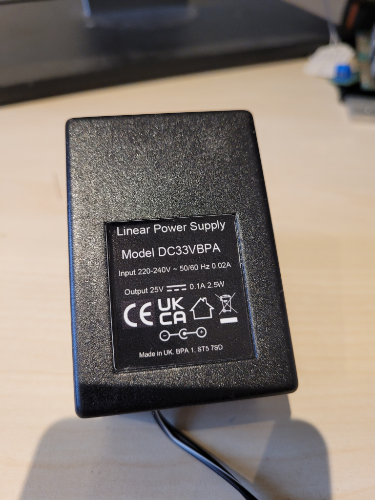
This contains a 3 VA transformer with a bridge rectifier and 470uF of reservoir capacitance. At a typical drain of 20mA, expect a ripple of 400mV pk-pk. At this load the PSU will be producing about 31V DC. Included inside is a simple mains filter which is an X rated capacitor across the mains input. The output cable is 1.2m and terminates in a DC barrel plug 5.5/2.1 mm. Standby power is about 1 Watt.
To make good preamp PSU simply add two 47R resisitors and two 1000uF capacitors.
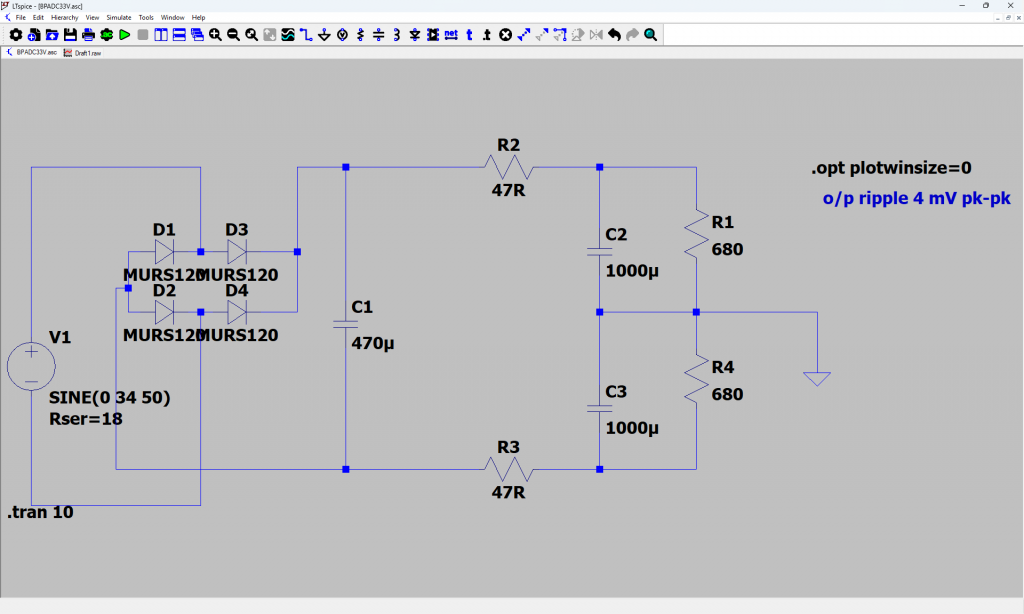
The two 680R resisitors represent the preamp load (c. 20mA). If the two preamp rails are unequal simply add an extra resisitor across the higher rail until equality is achieved. The components C1 and all to the left represent the BPADC33V ready built and tested PSU.
As an example take the Crimson CPR1, There are 4 dropper resisitors already on the PCB. As the Crimson only needs 10 mA, each of the 4 droppers (R25,R28,R125,R128) can be made 680R. The spaces for the rail decouplers (C23,C25,C123,C125) will acept 1000Uf at 16V. The over-voltage zeners (D5,D6) should be removed or changed to 18V types. However, the rails will be unequal as the preamp lacks PSU symmetry in terms of loading. This is because the voltage ref bleed via R2 from the negative rail does not balance the similar bleed from the postive via R5 and R105. If R2 is changed to be half the value of either R5 or R105 then the PSUs will balance and give rails of +/-14V and a ripple of 4mV pk to pk.
- use two rail droppers to give approx the correct voltage
- use two large capacitors to the centre tap to each rail
- load one or the other rails with a resistor to achieve voltage balance, or make PCB mods to equalise the PSU drain as per CPR1
Some preamps do not produce equally split rails using the resistor technique. So proceed as follows. Use the resisitor resisitor droppers with large capacitors. Measure the total rail voltage across the two capacitors. As an example, this could be 28V comprising +16V and -12V. Decide on two standard zener diode voltages just a few volts below the 28V. This can be two 13V zener diodes (500mW). Fit these in parallel with each large reservoir capacitor. Check thay do not heat excessively. Lower voltage zeners can be used if higher power ones are fitted. Check R2 and R3 do not overheat, thay should be touchable (with care).
Please contact via me via Contact – Brian Powell Audio if you would like to purchase the PSU called BPADC33V. This has DC plug with 5.5/2.1 barrel connector.